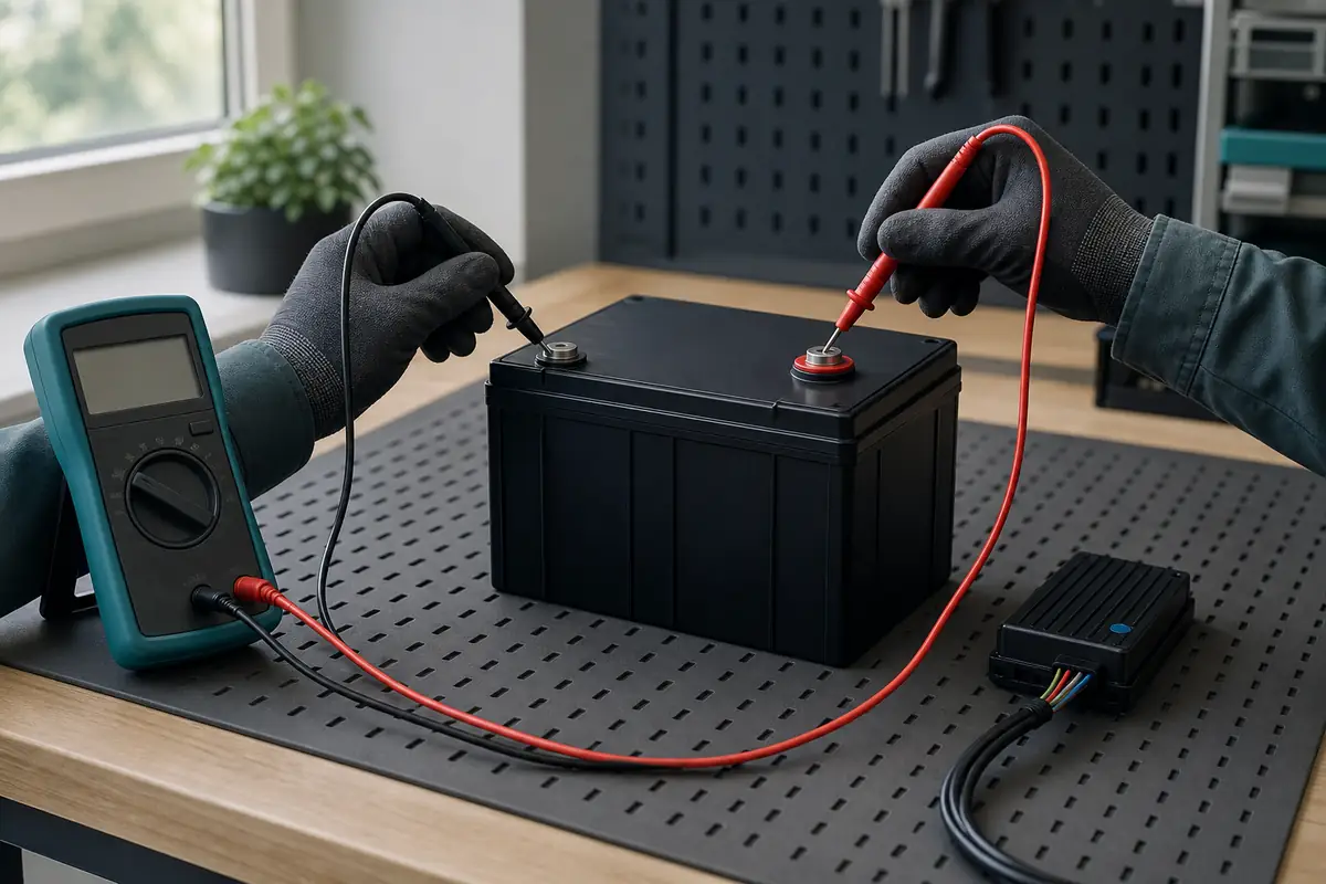
What a BMS test can and cannot prove
How to test a BMS is often used to mean two different jobs. A pack builder may want to confirm that the balance harness is in the right order and that the BMS sees each cell group. A service technician may need to verify a charge or discharge switch, a fuse, or a protection response. A multimeter is helpful for the first layer of checks, but it is not a universal BMS tester.
A voltage reading proves only the electrical difference between the two points you touched at that moment. It does not prove cell capacity, internal resistance, temperature-sensor accuracy, firmware logic, current-limit calibration, or safe operation under a real load. A normal reading can coexist with a weak cell, an intermittent connector, or a protection event that appears only during charging or acceleration. Keep those limits visible in your notes.
- Use the test to separate a wiring or sensing problem from a missing pack voltage.
- Use the exact BMS manual for port names, allowed ranges, and recovery behavior.
- Do not call a BMS bad because one output is absent before checking the pack and protection state.
- Do not use a meter test as a substitute for a qualified service procedure on a sealed or high-energy pack.
Gather the meter, records, and safety checks
For a basic BMS multimeter test, use a digital multimeter with leads rated for the pack voltage and category, insulated probe tips, eye protection, and a stable nonconductive work surface. Keep the charger, controller, motor, and other loads disconnected unless the manufacturer specifically requires a powered test. A notebook or spreadsheet helps you record the point names, polarity, reading, time, and pack condition without relying on memory.
Before touching a probe, read the BMS label and battery documentation. Confirm the chemistry, number of series groups, nominal and maximum voltage, connector pin order, common-port or separate-port design, and whether the maker allows user measurements. Remove rings and loose metal, keep one hand away from the pack when appropriate, and never let the probe tips bridge adjacent terminals.
Set the meter to DC voltage before connecting to a battery. Confirm the leads are in the voltage sockets, not the current socket. Start on a range above the expected value, keep the probes on insulated sections, and stop if the display is unstable, the leads heat up, or the pack shows physical warning signs. Continuity or resistance mode must never be used across an energized cell group unless the exact service manual explicitly says so.
- Check the meter and lead rating against the maximum pack voltage, not only the nominal label.
- Use a written measurement order so a misplaced balance lead is noticed early.
- Keep the original settings and app screenshots before changing any control.
- Ask a qualified technician to test packs that are sealed, high energy, damaged, or unfamiliar.
Inspect labels, fuses, and balance wiring first
A safe BMS test begins with a visual inspection. Look for a loose connector, a pin pushed back in the housing, damaged insulation, a discolored fuse holder, corrosion, solder that has lifted, or a balance wire routed to the wrong cell tap. Do not pull a harness out of a live pack to make the labels easier to read. If the pack has been opened or rewired, stop and compare every point with the manufacturer's diagram before energizing the BMS.
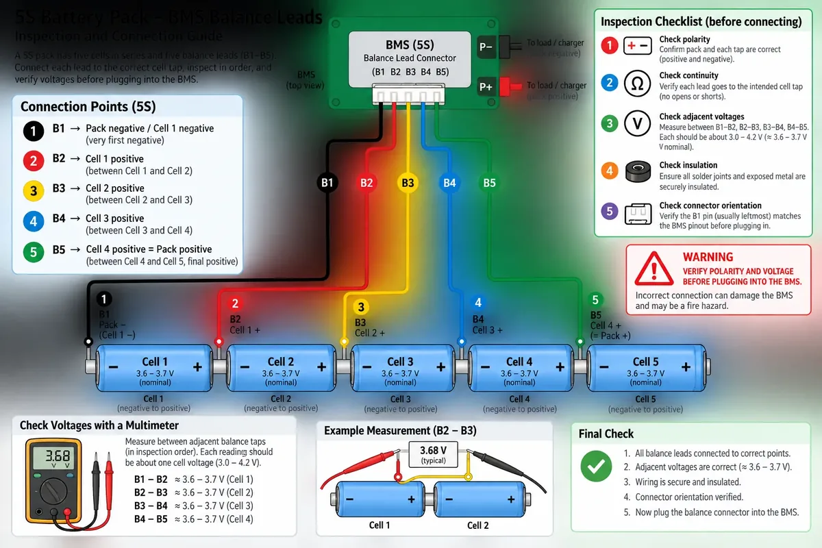
B-, P-, C-, P+, and balance labels are not universal. Some boards use a common negative port; others separate charge and discharge paths. A balance connector may label the first negative reference as B0, B1, or simply the black lead. The number printed on a board is not enough evidence to assume a different board uses the same order. Use the wiring guide for terminology, then follow the exact pinout for your model.
With the system disconnected and safe to inspect, trace the harness from the pack reference to each cell tap. The goal is to identify which adjacent points should equal one cell-group voltage. Do not plug a balance connector into the BMS merely because it fits. An incorrect polarity or order can damage the sensing circuit and create a fire hazard before any useful reading is taken.
- Photograph labels and connector orientation before moving a wire.
- Check the fuse and external connectors without touching hot or exposed metal.
- Mark an unknown or missing point as unavailable instead of inventing a reading.
- If the balance harness order is uncertain, stop and obtain a model-specific diagram.
Measure each cell group and the total pack voltage
To test BMS cell voltage sensing, use the documented negative reference and measure adjacent balance points in order. For a series pack, the difference between the first and second tap represents one cell group, the second and third represents the next, and so on. Write down each value with its point names and polarity. Do not compare an adjacent reading with a generic internet range without checking the chemistry and state of charge; a LiFePO4 group and a different lithium-ion group do not share the same voltage limits.
Next measure the total pack voltage at the approved pack terminals. The sum of the individual group readings should be close to the total, allowing for meter resolution and the manufacturer's measurement tolerance. A large mismatch suggests a wrong reference, a balance-lead or connector problem, a cell-group condition, or a BMS sensing fault. It does not identify which one by itself. Recheck the written point order and stop if a reading jumps unexpectedly.
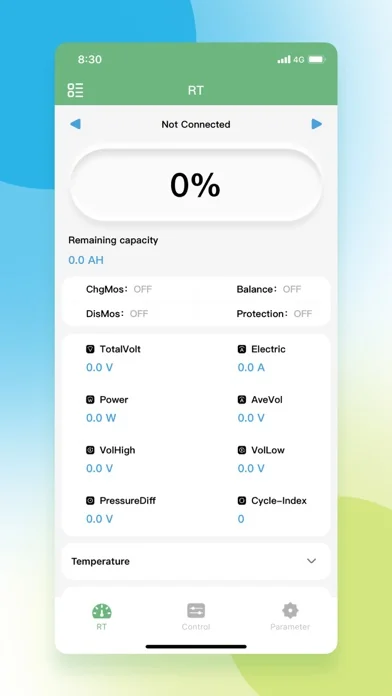
If an app is available, capture its live cell values at the same time. The meter and app may measure at different points or refresh at different moments, so small differences are not automatically a failure. A repeated, clearly implausible value, a missing group, or a change that appears only when the pack is loaded should be reported with the exact model and conditions. Do not keep charging a pack just to make the numbers look closer.
| Check | What to record | What it can suggest | What it cannot prove |
|---|---|---|---|
| Adjacent balance points | Point names, polarity, voltage, time | Whether each sensed group is present and in the expected order | Cell capacity or long-term health |
| Total pack terminals | Terminal names, voltage, charger/load state | Whether pack voltage exists at the approved output | That the BMS switches or protects correctly |
| Meter versus app | Two readings taken under similar conditions | A possible sensing, refresh, or wiring difference | Which instrument is correct without model specifications |
| Repeated measurement | Same points after a short, safe interval | An intermittent lead, connector, or unstable condition | Permission to continue if the pack becomes hot or damaged |
Check charge and discharge switching without forcing it
A BMS may use one common negative path or separate charge and discharge ports. That design changes where a normal output should appear and which path a charger or load uses. Identify the topology before checking a P- or C- terminal. The wiring guide can explain the names, but the exact BMS manual decides which terminal is safe to measure and what state the system must be in.
With the charger and load disconnected, first record pack voltage at the approved battery-side points. Then, only if the documentation allows it, compare the corresponding output point. A missing output can be caused by an active protection state, an open fuse, a disabled switch, a connector fault, or a missing pack reference. It is not automatically a failed MOSFET or control board.
Do not short an output to test overcurrent protection, place a wire across a switch, or raise a current limit to make a motor start. Protection validation with a controlled supply or load simulator belongs to a qualified lab procedure. For a home check, the useful result is a well-labeled difference between input and output plus the BMS warning or state that accompanied it.
- Record whether the test concerns charging, discharging, or both.
- Confirm the connector and port topology before choosing probe points.
- Treat a protected output as a state to explain, not a fault to bypass.
- Use a qualified service procedure for current, temperature, and threshold tests.
Compare readings and isolate the likely fault
The useful question is not only whether a number looks normal. Ask whether the same point, polarity, and condition were used for every comparison. If the pack-side total is present but the output is absent, document the protection state and external path. If every adjacent cell group is plausible but the app reports one impossible value, compare the harness, connector, reference point, and meter before blaming the cell. If one group is consistently different from the others, the cell group and its sense path both need attention.
A BMS test should narrow the next safe action. A wrong balance order points back to wiring. A missing pack voltage points to the pack, fuse, or connection before the BMS. A normal no-load output that disappears under load points toward current demand, voltage sag, temperature, controller behavior, or a protection threshold. A Bluetooth disconnect is a communication symptom; it is not proof that the power path stopped for the same reason.
Keep a small table with the test date, battery state, ambient condition, meter model, point names, reading, app warning, and next action. This record is more useful to a supplier than a single screenshot. Do not average away an outlier, delete a warning, or repeat the measurement until a preferred value appears. If the evidence is contradictory, stop and ask for model-specific service instructions.
- Compare like with like: the same points, polarity, load state, and instrument range.
- Separate a pack problem, a sense-wire problem, an output-path problem, and an app-communication problem.
- Use repeated safe observations to establish a pattern, not to stress the battery.
- Share the original readings and warnings when requesting support.
| Observation | Reasonable next question | Avoid |
|---|---|---|
| One group is absent or implausible | Is the reference, balance lead, connector, or cell group documented correctly? | Charging until the reading changes or swapping wires at random |
| Pack voltage exists but output is missing | Is protection active, is a fuse open, or is the port topology different? | Bridging the output or forcing a switch |
| Output drops only with a load | What are the startup demand, voltage sag, temperature, and warning state? | Increasing the BMS limit without verified ratings |
| App and meter disagree | Were they measured at the same points and time, and what does the manual specify? | Treating either screen or meter as an automatic health score |
Know the limits of protection tests and when to stop
Overvoltage, undervoltage, overcurrent, short-circuit, and temperature protection are functional behaviors, not ordinary continuity checks. Reproducing them with a live lithium pack can damage cells, weld a switch, create heat, or leave the pack in an unsafe state. Technical labs use controlled cell simulators, programmable supplies, calibrated loads, and a documented recovery plan. A household multimeter cannot safely replace that equipment.
For a user-level test, record the protection message, the conditions immediately before it, and whether the approved recovery procedure changes the state. Do not test a short by touching probes together across the pack. Do not use resistance mode on an energized circuit. Do not disable temperature or voltage limits because a test is inconvenient. The safest result may be an incomplete test with a clear service handoff.
Stop immediately for swelling, leakage, smoke, abnormal odor, unusual heat, exposed conductors, melted insulation, a rapidly changing cell reading, or a meter lead that becomes warm. Keep people away and follow the battery maker's emergency guidance. If the pack is physically normal but protection repeats at a modest load, contact the supplier or a qualified technician with the measurement log.
- Never short a pack or bridge a BMS output to prove overcurrent protection.
- Never charge or discharge a visibly damaged or hot battery to repeat a fault.
- Use manufacturer limits and a controlled test plan for threshold validation.
- A safe stop and accurate service record are valid test outcomes.
Prepare a service-ready BMS test record
Before contacting a supplier, turn the measurements into a short timeline. Include the battery chemistry and series count, BMS model and firmware if visible, charger and load models, whether the test was charging or discharging, and the exact point names. Add the date, meter model, range, polarity, reading, app state, warning text, and any physical observation. State which values were unavailable instead of filling them with estimates.
A good record lets another person reproduce only the safe parts of the check. It also prevents the common mistake of combining readings from different states of charge or different ports. Attach clear photos of labels and connector orientation only when the pack is safe to handle. Do not publish a serial number, location, or personal information with a public support request.
Use the related BAT BMS app manual to capture dashboard readings and the BMS wiring guide to name terminals. Use the reset guide only after the cause and model-specific recovery procedure are known. If you need to replace a BMS, stop treating a meter reading as a repair instruction; replacement requires chemistry, series count, current rating, port topology, temperature sensing, and mechanical compatibility checks.
- Write the measurement order so a technician can see exactly what was compared.
- Attach the original app warning and do not crop out the operating state.
- Separate measured facts, manufacturer specifications, and your interpretation.
- Ask for a documented next step before changing wiring or protection settings.
How to Test a BMS FAQ
Can I test a BMS with only a multimeter?
A multimeter can compare documented voltage points, cell groups, pack voltage, some fuses, and some output paths. It cannot validate every protection threshold, current limit, temperature sensor, firmware rule, or cell-health value. Use it as a first diagnostic layer and follow the exact BMS manual.
How do I test if a BMS is bad?
Do not decide from one missing output. Record the pack-side voltage, adjacent cell-group readings, balance harness order, port topology, protection state, and external fuse or connector condition. A repeated mismatch may identify a sensing or output-path problem, but a qualified person must confirm a hardware failure.
What voltage should I see on BMS balance leads?
Adjacent balance points should normally differ by approximately one cell-group voltage for the chemistry and state of charge, but the exact range comes from the battery and BMS documentation. Do not use a generic lithium-ion range for every pack or connect a harness based only on wire color.
Can continuity mode test a connected BMS?
Do not use resistance or continuity mode across an energized battery circuit unless the model-specific service manual explicitly permits that procedure. Start with safe DC-voltage checks and ask a qualified technician about any powered continuity test.
How can I test BMS overcurrent protection at home?
Do not create a short or force a large load to trigger overcurrent. Controlled protection validation needs rated equipment, a known test plan, and recovery steps. At home, record the load, warning, current information supplied by the system, and exact conditions, then request model-specific service.
Why do my BMS app and multimeter show different values?
They may measure different points, refresh at different times, use different references, or have a sensing or connection issue. Repeat only safe, documented comparisons under similar conditions. A difference is evidence to investigate, not proof that either instrument is automatically correct.
When should I stop testing a battery BMS?
Stop for swelling, leakage, smoke, abnormal odor, unusual heat, damaged insulation, exposed conductors, a rapidly changing cell value, or a warm meter lead. Also stop when the next check would require opening a sealed pack or bypassing protection. Preserve the safe readings and contact the manufacturer or a qualified technician.
Technical references
- Keysight: Automotive BMS Validation with a Four-Channel DC Power Supply - Application note covering controlled validation of cell balancing, overvoltage, and undervoltage behavior.
- Texas Instruments: Cell balancing fundamentals - Background on series-cell imbalance and why balancing behavior depends on the design.
- Pickering Interfaces: BMS testing guide - Explains why controlled cell simulation is used for repeatable development and production tests.
- BAT BMS app on Google Play - Official app listing referenced for app-state and dashboard context.