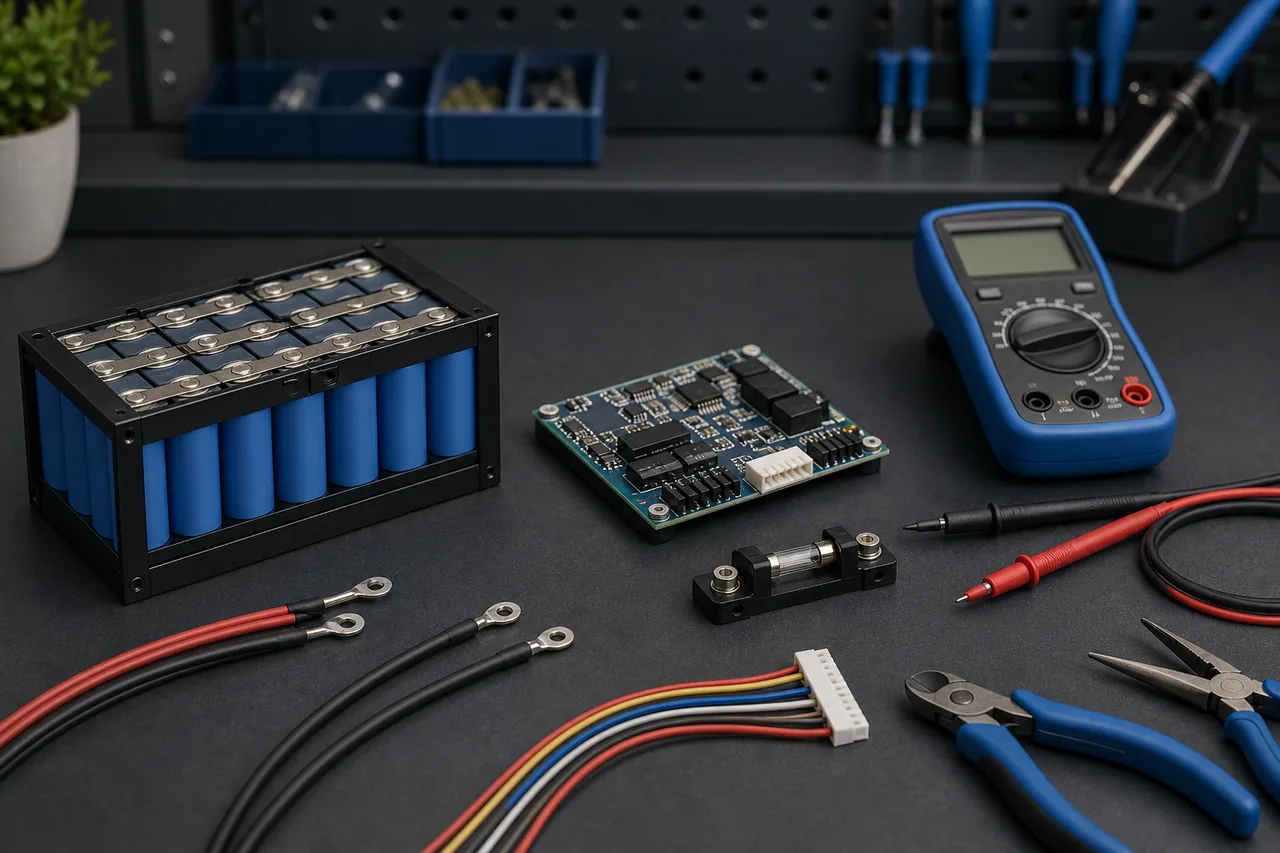
1. Start with the exact BMS wiring diagram
A search result for BMS wiring can teach the vocabulary, but it cannot replace the manual for your board. Photograph both sides of the BMS, record every printed label, connector key and model number, and compare those details with the manufacturer document. Boards with the same cell count may still use different negative terminals, harness pin orders, temperature sensors or communication sockets.
Do not infer a terminal from cable color alone. Some harnesses are repinned by sellers, repaired packs may not follow the original color sequence, and a connector can sometimes be inserted offset or reversed. Treat labels, continuity checks and measured voltage as evidence; treat color only as a convenience.
- Remove charger and load before continuity or harness checks.
- Cover exposed positive terminals and remove metal jewelry.
- Verify the pack series count matches the BMS rating before connection.
- Keep the balance connector unplugged from the BMS during sequence measurements.
| Common label | Typical role | What must be verified |
|---|---|---|
| B- | Battery-pack negative connection | Board manual, cable gauge and direct continuity to pack negative |
| P- | Controlled negative path for load and sometimes charger | Whether the board is common-port and which devices share this path |
| C- | Separate controlled charger-negative path on some boards | Whether C- exists and whether it is charge-only |
| B0/B1... or balance plug | Cell-junction sensing | Pin 1, connector orientation, cell count and rising voltage sequence |
| B+ or pack positive | Often a direct positive path outside the BMS switching side | Fuse position and the exact manufacturer diagram |
2. Common-port and separate-port BMS wiring are different
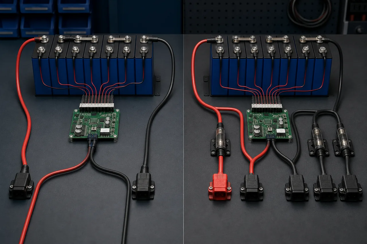
A common-port BMS usually routes charge and discharge negative through the same controlled terminal, often P-. A separate-port board normally gives the charger its own controlled negative terminal, often C-, while the load uses P-. These descriptions are common patterns, not permission to connect by label alone.
The practical consequence is troubleshooting behavior. On a separate-port design, charging may still work when discharge protection is active, or the reverse. On a common-port design, one switched path may affect both directions. Confirm the topology before diagnosing a charger, inverter or motor controller as faulty.
| Design | Charger negative | Load negative | Main check |
|---|---|---|---|
| Common port | Usually P- | Usually P- | Shared current rating and one controlled path |
| Separate port | Often C- | Usually P- | Charge-port rating and model-specific limits |
| Unknown or unlabeled | Do not guess | Do not guess | Find the exact manual or stop |
3. Verify every balance lead in sequence
The balance harness lets the BMS read individual cell groups. A typical series pack begins with a reference at pack negative, then adds one cell-group voltage at each next wire until the final wire reaches pack positive. The exact connector pin order is model-specific, so identify the first pin from the board documentation rather than assuming the left or right side.
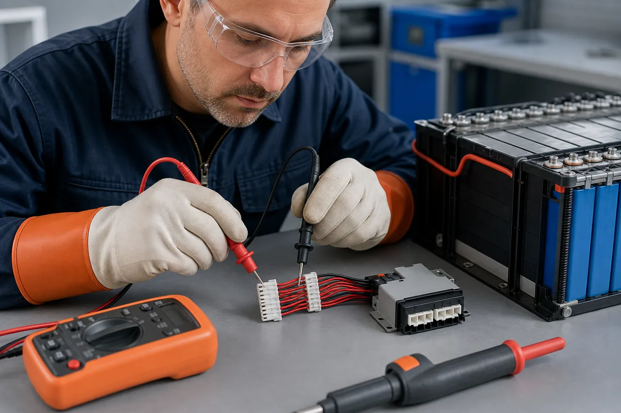
With the harness disconnected from the BMS, use a suitable meter to check adjacent wires in order. Each adjacent step should resemble one cell-group voltage, and the cumulative reading from the reference wire should rise steadily. For LiFePO4, an adjacent step near the normal cell voltage is expected; a negative step, zero step, doubled step or sudden pack-level jump means the sequence needs correction before connection.
- Secure one probe so it cannot slip across neighboring pins.
- Record each adjacent and cumulative reading instead of relying on memory.
- Inspect for duplicated, skipped or reversed cell junctions.
- Do not insert or remove the harness while the main negative connection is in an unknown state.
| Meter result | Likely meaning | Action |
|---|---|---|
| Small positive step at each adjacent pair | Sequence may be correct | Continue and compare all readings with the manual |
| Negative voltage | Lead order or probe direction is reversed | Stop and identify the reference wire |
| Near zero between two steps | Same junction, open lead or poor contact | Inspect connection before proceeding |
| Roughly two cell groups in one step | A junction may have been skipped | Correct the harness mapping |
| Unexpected pack voltage at one pin | Wrong pin, orientation or harness | Do not connect the plug |
4. Size power cables, fuse and terminals for the real current
Correct labels do not make an undersized connection safe. Continuous current, surge current, cable length, ambient temperature, terminal quality and enclosure ventilation all affect heating. Use the battery, BMS and equipment limits together; the lowest verified continuous rating is the system limit.
Place the main fuse according to the battery or system designer's instructions, normally close enough to the source to protect the conductor. A BMS is not a replacement for overcurrent protection against a short in wiring that bypasses its controlled path. Crimp terminals with the correct tooling, insulate exposed lugs and add strain relief so vibration cannot work a cable loose.
- Do not put a smaller charger or load connector on a cable expected to carry the full current.
- Avoid stacking uncontrolled numbers of ring terminals on one battery post.
- Recheck torque using the hardware maker's value, not guesswork.
- Stop a test if a cable, lug, fuse holder or board becomes unusually warm.
5. Use a controlled first power-up checklist
Before connecting the balance plug, compare the measured total with the pack voltage and confirm the connector orientation one final time. Follow the board's required connection order; some manuals specify the main negative connection before the balance harness, while other systems include a precharge or wake-up procedure. Do not invent the order from another brand's video.
For the first test, keep high-power loads disconnected. If the manufacturer allows it, use an appropriate current-limited or fused setup, then verify pack voltage at the expected output before attaching a charger or load. In a compatible monitoring app, plausible cell voltages, temperatures and total voltage are useful checks, but an app screen cannot prove that cable gauge, fuse placement or terminal torque is safe.
- Check for reverse polarity before every connector is inserted.
- Confirm all displayed cell groups exist and are in a plausible range.
- Investigate a missing cell, impossible temperature or large unexplained cell spread.
- Add the charger and load one at a time so a fault has a clear cause.
6. Troubleshoot the circuit without bypassing protection
If the output is off, first determine whether the BMS sees undervoltage, overvoltage, overcurrent, temperature or a missing-cell condition. Measure pack voltage, controlled output voltage and charger voltage with respect to the correct reference point. A zero reading at P- does not automatically mean the board is defective; it may be protecting the pack or waiting for a documented wake-up condition.
Do not bridge B- to P-, bypass MOSFETs, move a balance wire while connected, or repeatedly reset the board until output returns. Those actions can remove the only barrier between an unsafe cell condition and a high-current load. Use the safe reset guide only after the original protection cause has been identified.
- Wrong total voltage: recheck series count and reference points.
- One cell group missing: inspect the matching junction and harness pin.
- Charge works but load does not: confirm separate-port topology and discharge protection status.
- App connects but values are implausible: stop; connectivity is not proof of correct wiring.
7. Stop when the documentation or measurements disagree
Professional help is the correct next step when the model cannot be identified, the pack has damaged insulation, swollen cells, corrosion, burned terminals, an unknown previous repair or voltage that changes unexpectedly. High-energy lithium packs can deliver destructive fault current even when the nominal voltage seems modest.
A useful BMS wiring guide should reduce guessing, not encourage confidence without evidence. Keep a written map, meter readings, photos and the exact manual with the battery. If any connection cannot be explained before power is applied, leave it disconnected.
BMS Wiring FAQ
What do B-, P- and C- mean on a BMS?
B- commonly connects to pack negative. P- commonly serves the controlled load negative and, on common-port boards, the charger negative. C- commonly serves a separate charger-negative path. Confirm all three in the exact model manual because labels and topology can vary.
Can I connect a BMS using wire colors only?
No. Colors may be inconsistent, modified or reversed. Use the board labels, connector orientation, continuity checks, measured voltage sequence and manufacturer diagram.
In what order should BMS balance wires be connected?
A typical harness progresses from the pack-negative reference through each cell junction to pack positive, but connector pin order is model-specific. Measure every adjacent and cumulative step while the plug is disconnected, then follow the manufacturer's stated connection order.
What happens if a BMS balance wire is connected incorrectly?
A reversed, skipped or misplaced lead can produce wrong cell readings and may damage the BMS as soon as the harness is inserted. Stop when any step is negative, near zero, doubled or otherwise inconsistent.
Does the positive battery cable pass through the BMS?
Many low-side BMS designs switch the negative path while pack positive goes directly to the load and charger through appropriate protection, but this is not universal. Follow the model-specific diagram and fuse design.
Why does a newly wired BMS show no output?
Possible causes include active protection, wrong connection order, an incorrect balance sequence, a missing wake-up condition, undervoltage, temperature limits or a genuine fault. Do not bypass B- to P-; diagnose measurements and protection status first.
Technical references
- Victron Energy Wiring Unlimited - DC cable, fuse, voltage-drop and connection guidance.
- Texas Instruments battery-management overview - Primary technical context for battery monitoring, protection and balancing.
- BAT BMS on Google Play - Official Android app identity for compatible monitoring references; not a wiring manual.