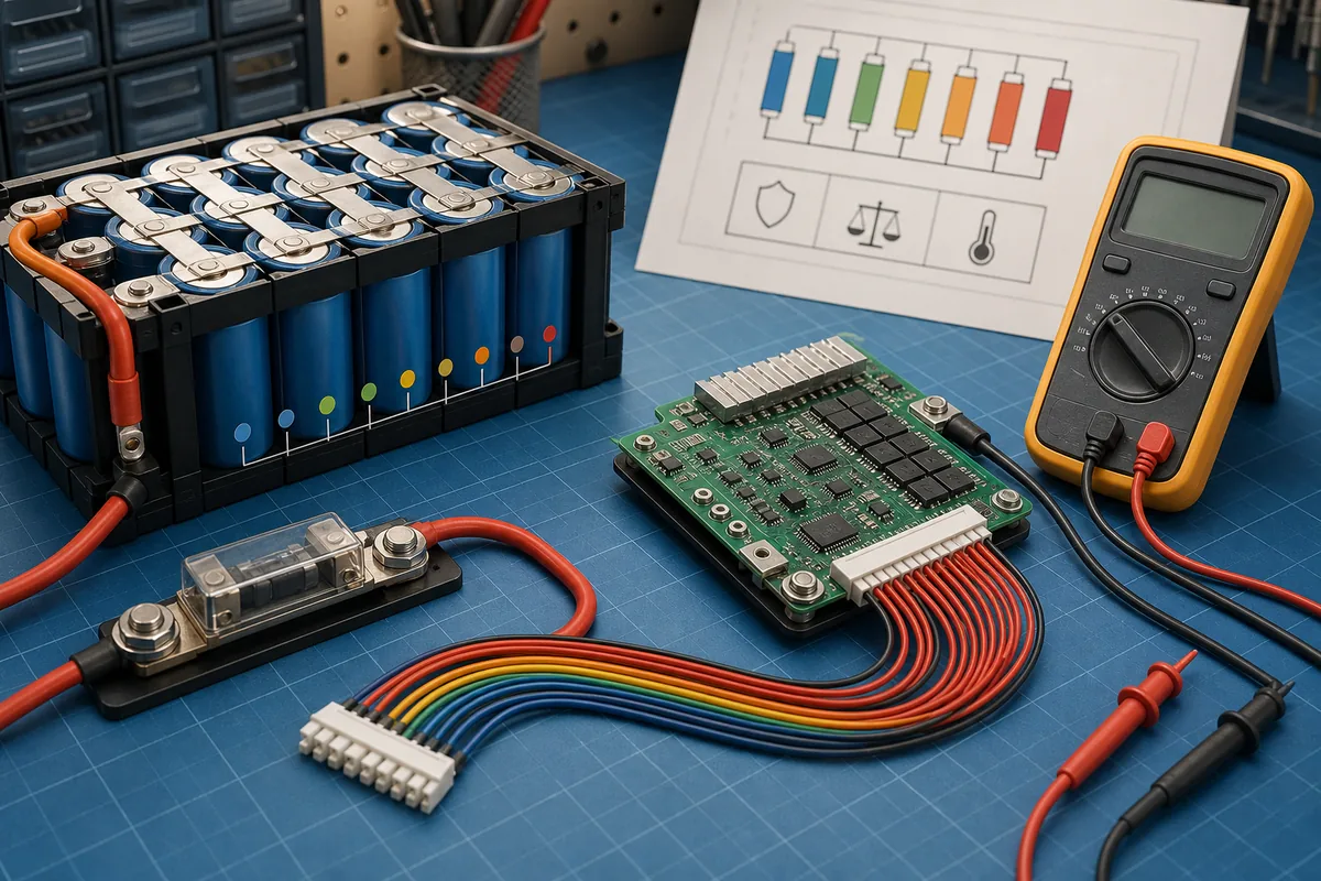
1. Start with chemistry and series count
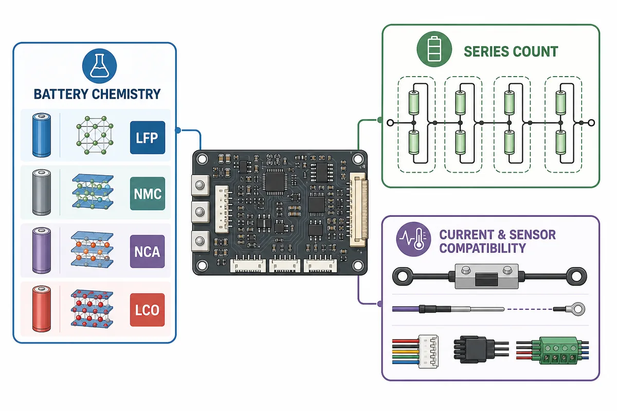
The first decision for a BMS for lithium battery use is chemistry. LiFePO4, NMC, LCO and other lithium cell families have different charge limits, protection thresholds and balancing behavior. A board that looks suitable because the voltage is similar can still be wrong for the cells. Record the exact chemistry from the cell or battery documentation before looking at marketplace ratings.
Next, confirm the series count, often written as 4S, 8S, 12S or another value. The series count determines the nominal pack voltage, the full-charge voltage range and the number of balance groups the BMS must measure. A label such as 48 V is not enough by itself because different chemistries and pack designs can use different cell counts. Count groups where possible and compare the result with the manufacturer's diagram.
- Write down chemistry, nominal voltage, series count and the maker's maximum charge voltage.
- Do not infer cell count from the external case or from a charger label alone.
- If the label and measured group count disagree, stop and resolve the discrepancy before ordering a board.
| Check | Record | Why it changes the BMS choice |
|---|---|---|
| Cell chemistry | LiFePO4, NMC, LCO or documented equivalent | Charge, discharge and protection thresholds are chemistry-specific. |
| Series count | Actual S count and nominal pack voltage | The board must measure the right number of cell groups. |
| Cell and pack limits | Maximum charge, discharge and temperature limits | The BMS settings must stay inside the cells' safe operating range. |
2. Match continuous and peak current to the whole power path
A BMS current number is not automatically the safe output of the battery. Compare the cell discharge limit, BMS continuous rating, cable gauge, fuse, connector, busbar, charger, inverter or motor controller and the expected load. The lowest credible continuous limit usually controls the system. If one component heats, trips or falls outside its specification, a larger BMS label does not solve the problem.
Separate continuous current from short peak current and from charge current. A motor may draw a brief startup surge, while an inverter may create a different demand than its steady wattage suggests. Estimate current from the real operating voltage and load, then use the battery maker's documented margin rather than applying a universal percentage to every pack. Check the BMS data sheet for whether its rating is continuous, peak, charge-only or discharge-only.
- Compare both charge and discharge ratings; they are often different.
- Check the time basis for a peak rating and the temperature at which the rating applies.
- Treat cables, fuse holders, lugs and connectors as part of the BMS safety decision.
| Rating | Compare it with | Safe interpretation |
|---|---|---|
| BMS continuous discharge | Cell, cable, fuse and load limits | Use the lowest supported continuous value, with the maker's documented margin. |
| BMS peak discharge | Startup or surge duration | Do not use a short peak number as a continuous load target. |
| Charge current | Charger, cells, temperature and charge port | Charging can need a separate limit and a low-temperature cutoff. |
3. Confirm ports, balance harness and sensors
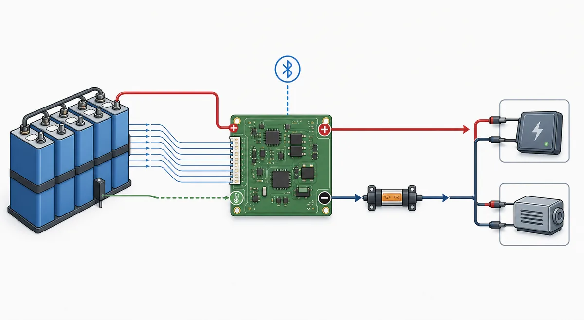
Many BMS mistakes happen after the correct chemistry and current board is chosen. Confirm whether the board uses a common port or separate charge and discharge ports, then compare the actual negative paths with the manual. A connector that fits physically is not proof that the pinout, balance-wire order or temperature-sensor type is compatible.
Check the number and order of balance leads, the connector keying, the main negative terminal, charge and load terminals, temperature probes, communication ports and mounting clearances. If the pack uses Bluetooth, CAN, UART or another interface, verify that the board, app and cable or antenna use the same protocol. Keep the exact model diagram with the pack instead of relying on a photograph from a different board.
- Match the connector and pinout, not just the connector shape.
- Confirm sensor quantity, sensor type, cable length and where each probe should sit.
- Leave room for insulation, strain relief and cooling around the BMS board.
4. Compare balancing and protection settings
A suitable BMS should provide the protections that the battery design needs: cell overvoltage and undervoltage, charge and discharge overcurrent, short-circuit response, and temperature protection where applicable. Read the data sheet for the actual thresholds and recovery behavior. Do not copy a screenshot or password-protected parameter set from another battery just because the board name looks similar.
Balancing is another compatibility check, not a cure for a weak or damaged cell. Passive balancing may start only near the top of charge and only when the voltage difference reaches a configured condition. The app can show cell values or a balance control on compatible hardware, but a visible switch does not prove that balancing is active or that every chemistry uses the same threshold.
- Confirm overvoltage, undervoltage, overcurrent and temperature behavior for the actual chemistry.
- Ask whether balancing is passive or active, when it starts and what current it can move.
- Use cell voltage spread as a clue for investigation, not as a single battery-health verdict.
5. Use a compatibility checklist before purchase
Before ordering, put the battery information and the board information in one comparison sheet. If you are comparing a battery pack with BMS, ask for the chemistry, series count, current limits and wiring diagram rather than relying on the product title. The goal is to prove compatibility, not to find the biggest current number at the lowest price. A listing that omits the full wiring diagram, firmware behavior, sensor specification or recovery conditions creates uncertainty that an attractive specification table cannot remove.
For a replacement or custom pack, also check physical dimensions, mounting holes, insulation, heat dissipation, connector availability, app support and whether the manufacturer provides a real service procedure. If the board is intended for a high-voltage pack, a sealed certified battery or a system with contactors, field replacement may not be an appropriate DIY task.
- Chemistry and series count match the actual cell groups.
- Continuous, peak, charge and temperature ratings match the complete system.
- Ports, balance connector, sensors, communication and firmware are documented.
- Board dimensions, insulation, fuse path and cooling are physically workable.
- The seller or maker can provide a model-specific diagram and support path.
6. Keep the first installation and test controlled
Before moving a wire, isolate the battery and document the old arrangement with photographs, measurements and labels. Follow the new board's stated connection and disconnection order, especially for the balance harness. Keep the first power-up unloaded or at the lowest controlled test condition allowed by the maker, then check total voltage, each group, temperature, protection status and unexpected heating.
Stop when a cell group is missing, doubled or negative, when a sensor reading is impossible, when a cable or terminal heats quickly, or when the pack is swollen, wet, burned or mechanically damaged. A normal total voltage does not prove that the balance mapping is correct. If the model diagram and your measurements disagree, leave the pack isolated and use qualified service rather than guessing.
- Record the original readings and settings before any service work.
- Perform a low-risk verification before connecting a high-power load or charger.
- Do not bypass a protection path to make an unknown installation appear to work.
7. Use BAT BMS as a verification tool, not a selection shortcut
After a compatible board is installed, BAT BMS can help you observe live values such as pack voltage, cell readings, current, temperature and protection state when the hardware supports the app. Battery management systems cover many board designs, but the practical question behind a search for BMS in lithium battery applications is still whether the controller matches the cells and protection path. Read related values together and compare them with a known test method. The app is a monitoring interface; it cannot identify an unknown pinout, repair a damaged cell or make an incorrectly rated BMS safe.
For a practical handoff, save the BMS model, chemistry, series count, current limits, wiring diagram, sensor locations and baseline readings with the battery. If the app shows a repeated protection event or a large unexplained cell difference, pause charging or loading and investigate the electrical cause before changing settings.
- Use the app manual for connection and screen terminology.
- Use the wiring guide for model-specific terminals and balance leads.
- Use the balancing and replacement guides when the issue is cell spread or a failed board.
BMS for Lithium Battery FAQ
How do I choose a BMS for a lithium battery?
Match the cell chemistry, series count, continuous and peak current, charge and discharge ports, balance harness, temperature sensors, protection thresholds and communication interface. Verify the exact battery and BMS diagrams before connecting anything.
Can I use any BMS with a LiFePO4 battery?
No. A LiFePO4 pack needs a BMS whose chemistry thresholds, series count, current limits, sensors and wiring are compatible with the actual cell groups. A similar voltage label or connector shape is not enough.
Does a higher-amp BMS make a battery more powerful?
No. The usable current is limited by the cells, BMS, cables, fuse, connectors, temperature and load equipment. A higher BMS rating cannot safely raise a weaker cell or wiring limit.
What is the difference between a common-port and separate-port BMS?
A common-port design shares a current path for charging and discharging, while a separate-port design provides different charge and discharge paths. The terminals and negative paths must be confirmed from the exact model diagram.
Can BAT BMS tell me whether a BMS is compatible?
The app can show data from compatible hardware, but it cannot validate an unknown pinout, chemistry setting or installation. Use the battery and BMS documentation first, then use BAT BMS to observe readings after a controlled connection.
When should I stop trying to install a BMS myself?
Stop when the pack is swollen, leaking, wet, burned, mechanically damaged, sealed under warranty, high voltage, or electrically unexplained. Also stop when the wiring diagram and measurements disagree. Use the manufacturer's service channel or a qualified battery technician.
Technical references
- Texas Instruments battery management overview - Primary context for monitoring, protection, gauging and balancing functions.
- Victron Energy Wiring Unlimited - Reference for DC wiring, fuses, connection resistance, cable sizing and voltage drop.
- DALY BMS battery selection notes - Manufacturer-side context for matching BMS selection to battery design rather than capacity alone.