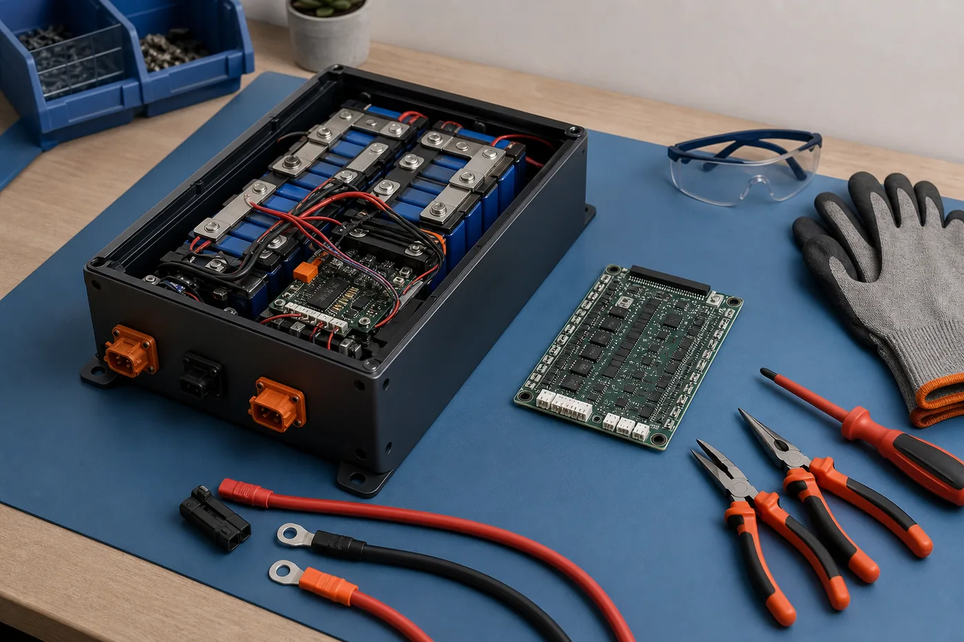
1. Confirm the BMS actually needs replacement
A battery that will not charge or discharge does not automatically have a failed BMS. The board may be correctly blocking output because one cell group is too low or too high, a temperature sensor is open, a current event was recorded, the balance harness is loose, or a charger is not reaching the required voltage. Replacing the board without finding the trigger can hide the evidence and expose the same cells to a second fault.
Measure total pack voltage at the cells and at the controlled output, then compare every cell group. Inspect fuses, connectors, temperature probes and cable joints. If a compatible app reports protection status, use it as another clue, not as the only diagnosis. A reset or manufacturer-approved wake-up may be appropriate when the cells are healthy and the protection cause is understood; repeated bypassing or blind resets are not diagnosis.
Replace the BMS only when the board is confirmed incompatible, physically damaged, unable to switch despite valid inputs, or missing features the pack legitimately requires. Do not reuse a battery after smoke, electrolyte odor, melted insulation, water ingress or a cell that will not hold a stable voltage.
- Record total pack voltage and every cell-group voltage before disconnecting anything.
- Check whether charge and discharge paths fail separately on a separate-port design.
- Inspect the balance connector for a backed-out, corroded or reversed pin.
- Stop if the enclosure contains swollen cells, heat damage, moisture or undocumented modifications.
2. Choose a replacement BMS that matches the pack
The replacement must be designed for LiFePO4, not merely described as a lithium BMS. LiFePO4 cell voltage limits differ from common NMC or lithium-ion settings. Match the number of series cell groups: a 12.8 V nominal pack is commonly 4S, while a nominal 38.4 V LiFePO4 pack is commonly 12S, but the measured pack and manufacturer label must decide the configuration.
Current rating must cover the real continuous load and expected surge without exceeding the safe limits of the cells, conductors, connectors and fuse. A higher printed current number does not upgrade the rest of the battery. Also compare common-port or separate-port topology, cable gauge, balance connector pinout, number and type of temperature sensors, low-temperature charge cutoff, Bluetooth or CAN/RS485 communication, and any required external contactor or precharge circuit.
Connector shape is not proof of electrical compatibility. Two plugs can fit while using a different pin order. Obtain the pinout for both boards and create a transfer map. If the new board lacks documentation or its protection thresholds cannot be verified for the cell maker's limits, it is not a safe substitute.
| Compatibility item | What must match | Why it matters |
|---|---|---|
| Chemistry | LiFePO4 charge, discharge and balancing thresholds | Wrong limits can overcharge or over-discharge cells |
| Series count | Exact number of monitored cell groups | A wrong count creates missing or misread cells |
| Current | Continuous, surge and charge current within the whole system limits | Undersized switches and cables can overheat |
| Port layout | Common port or separate charge/discharge ports | Determines where charger and load negatives connect |
| Harness and sensors | Pin order, connector key and temperature probe type | A fitting connector can still be electrically wrong |
| Communication | Bluetooth, CAN, RS485 or none as required | The battery or equipment may depend on a specific protocol |
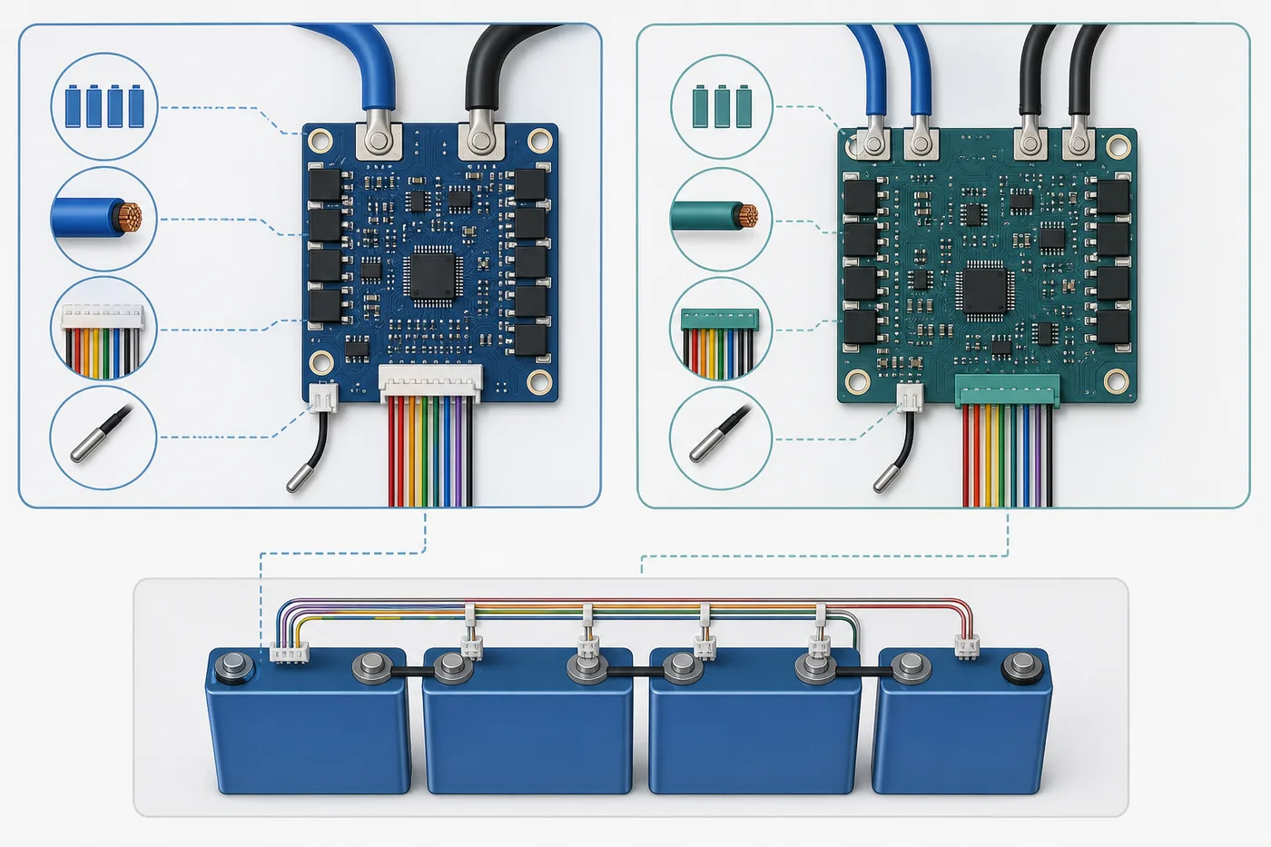
3. Isolate the battery and document every connection
Work in a dry, nonconductive area with the charger, inverter, motor controller and other loads physically disconnected. Remove jewelry, protect exposed positive points, and keep insulated covers available for every loose lug. High-energy packs can deliver destructive fault current even when their nominal voltage is below common high-voltage definitions.
Before removing a connector, photograph the full pack and close views of B-, P-, C-, pack positive, fuse, balance plug, temperature probes and communication cables. Label wires outside the enclosure, record cable gauge and terminal positions, and draw a simple map. Measure adjacent balance-lead steps and the cumulative voltage from the reference lead while the plug is disconnected from the BMS. The cumulative reading should progress consistently with the cell groups.
Do not cut multiple conductors together and do not leave an uncovered lead where it can spring back onto a terminal. If the pack has welded busbars, sealed modules, potting compound, an active contactor system or an undocumented high-current layout, ordinary board replacement guidance is not enough.
- Use one-handed probe technique where practical and prevent probe tips from bridging adjacent pins.
- Write down measurements instead of relying on photos or memory alone.
- Keep removed fasteners and insulating sheets in their original positions.
- Do not continue if wire identity and measured voltage disagree.
4. Follow the documented disconnect and install order
There is no safe universal statement such as 'always unplug the balance connector first' or 'always remove B- first.' Manufacturers use different precharge paths, contactors, communications and input protection. Read both the battery service information and the replacement-board manual, then follow the stated sequence. If they conflict or one is unavailable, stop rather than borrowing the order from a different brand's video.
Transfer one identified connection at a time. Prevent each loose cable from touching another terminal, the enclosure or the board. Mount the BMS on the specified insulating and heat-spreading surface, preserve airflow, avoid pressure on small components, and provide strain relief. Reuse a temperature probe only when its electrical type and location are compatible with the new board.
Before inserting the balance harness, compare its total measured voltage with pack voltage and verify every adjacent step again. Confirm connector orientation and pin 1 from documentation. A reversed, skipped or duplicated balance lead can damage the new board immediately or report a plausible but wrong cell map.
- Never use cable color as the only mapping method.
- Do not bridge B- to P- to force output during installation.
- Do not place an uninsulated BMS directly against conductive casework.
- Replace damaged lugs, insulation, connectors and sensors instead of hiding them under the new board.
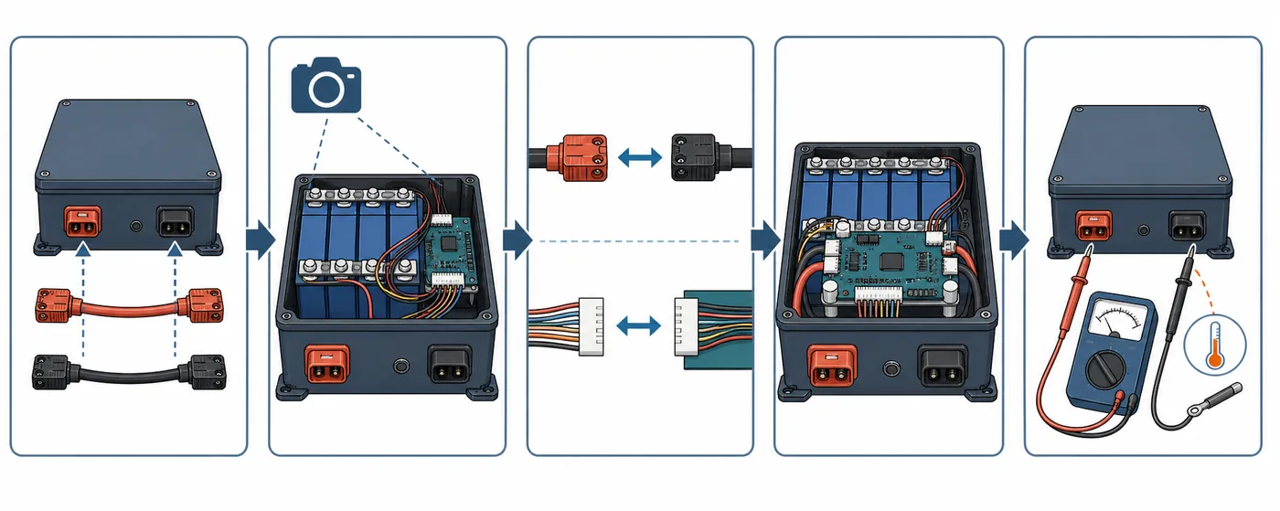
5. Perform a controlled first power-up
Keep high-current loads disconnected for the initial check. After completing the documented connection sequence, measure raw pack voltage and controlled output voltage with the correct reference points. Confirm that the BMS reports the expected number of cells, plausible individual voltages, total voltage and believable temperatures. A missing cell, reversed reading, impossible temperature or large unexplained difference is a stop condition.
If the manufacturer requires a charger or wake signal, use the specified method and voltage. Do not improvise with a higher-voltage charger. Add the charger and a modest load separately so the effect of each connection is clear. Monitor the BMS, cables, terminals and fuse holder for heat while staying within the maker's test procedure.
Only close the enclosure after the battery passes static measurements and a controlled functional test. Restore insulation barriers, cable routing, strain relief, temperature-probe placement and fastener torque. Keep the original readings, new BMS model, settings and installation date with the battery record.
| First-check result | Meaning | Action |
|---|---|---|
| All expected cells appear with plausible voltage | Harness mapping may be correct | Continue with the documented low-power test |
| One cell is missing, negative or doubled | Pin order or connection error | Disconnect according to the manual and recheck the map |
| Pack voltage is present but controlled output is off | Protection, wake requirement or installation fault | Read status and diagnose; do not bypass |
| Temperature is impossible or unstable | Wrong probe type, damaged sensor or connector problem | Stop and correct sensor compatibility |
| Cable, lug or board heats quickly | Excess resistance, overload or fault | Remove load and inspect before reuse |
6. Configure protection without copying generic values
A programmable BMS still needs limits based on the actual cells, pack design and equipment. Do not copy screenshots from another battery or maximize every threshold to prevent nuisance shutdowns. Cell overvoltage and undervoltage limits, recovery points, current limits, temperature cutoffs and balancing behavior should remain inside the cell manufacturer's operating limits and the battery builder's design.
Preserve factory settings when the replacement is an approved service part. For a custom pack, document each change and verify that charger, inverter or motor-controller limits cooperate with the BMS rather than repeatedly driving it into emergency protection. Low-temperature charging protection is especially important for LiFePO4 in cold environments.
Bluetooth access can make checking easier, but app connectivity does not validate wiring, fuse protection or thermal design. Protect administrative settings with appropriate credentials when the board supports them and avoid exposing control access to unknown nearby users.
7. Know when this is not a DIY replacement
Use qualified service when the pack is sealed or under warranty, the manufacturer prohibits field repair, cells are swollen or leaking, insulation is carbonized, the pack has been submerged, busbars require welding, the system uses high-voltage contactors, or the wiring cannot be positively identified. A successful app connection or normal total voltage does not remove these risks.
A careful BMS replacement is a measurement and compatibility job, not a wire-for-wire guess. The safest decision may be replacing the complete certified battery or using the original manufacturer's service channel. If any step depends on assuming what a connector does, leave the pack isolated until documentation or professional testing resolves it.
LiFePO4 BMS Replacement FAQ
Can I replace a LiFePO4 BMS with a higher-amp model?
Only when chemistry, series count, thresholds, port layout, harness, sensors and communication are compatible. A higher BMS current rating does not increase the safe current of the cells, busbars, cables, connectors or fuse.
What BMS is used for a 38.4 V LiFePO4 battery?
A 38.4 V nominal LiFePO4 pack is commonly 12S because 12 groups at about 3.2 V nominal equal 38.4 V. Confirm the actual series count, cell chemistry and manufacturer documentation before choosing a 12S board.
Can I reuse the old balance connector on a new BMS?
Only if the connector, pin count, keying, wire order and electrical pinout are verified for the new board. A plug that physically fits can still be wired differently and damage the BMS.
Why does the new BMS show no output?
Possible causes include an active protection state, wrong connection order, missing wake condition, incorrect balance mapping, sensor incompatibility, undervoltage or a defective installation. Diagnose the status and measurements; do not bypass B- to P-.
Should I disconnect the balance plug or main negative first?
Follow the exact battery and BMS service documentation. Connection and disconnection order is model-specific, so a universal answer can damage some boards or defeat a required precharge or contactor sequence.
When should a LiFePO4 battery be replaced instead of repaired?
Replace or professionally evaluate the complete battery when cells are swollen, leaking, unstable, burned, wet, mechanically damaged, deeply imbalanced without a known recoverable cause, or enclosed in a non-serviceable certified assembly.
Technical and safety references
- Victron Energy Wiring Unlimited - DC wiring, fuse, connection resistance and voltage-drop guidance.
- Texas Instruments battery management overview - Primary technical context for cell monitoring, protection, gauging and balancing.
- Progressive Dynamics BMS replacement guide - Manufacturer repair context emphasizing organized disassembly, documentation and verification.
- Victron Lithium NG battery manual - Example of model-specific installation, connection-order and communication requirements.