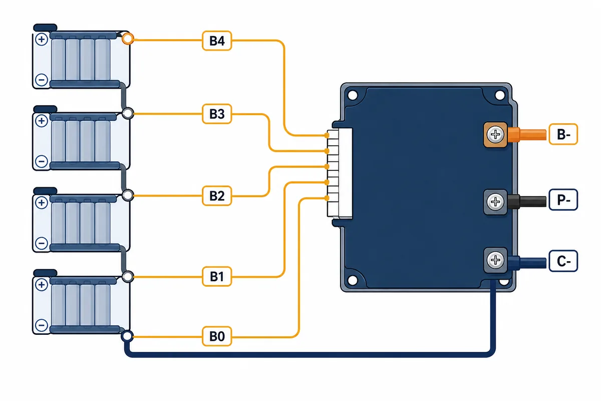
1. Start with the exact Daly BMS wiring diagram
DALY sells standard, smart, high-current, active-balancing and other BMS variants. Their connector layout, temperature sensor socket, communication port, wake-up method and negative switching path can differ even when the board looks similar. Start by recording the model label, chemistry, rated series count, current rating and the connector key. Photograph both sides of the board before removing any wire.
A generic diagram is useful for vocabulary, but it cannot prove that a specific DALY board uses the same balance order. Do not copy a wire-color chart from another seller. Compare the board silkscreen, the official model document and the physical battery nodes. If any of those disagree, leave the harness disconnected until the model is identified.
- Confirm LiFePO4 or other chemistry and the exact series count before wiring.
- Record the model number, connector key, sensor sockets and communication ports.
- Disconnect charger and load, cover exposed terminals and remove metal jewelry.
- Treat the official DALY drawing as the final authority for pin order and power-up sequence.
| Diagram element | Typical meaning | What to verify |
|---|---|---|
| S count | Number of cell groups in series | Chemistry, nominal voltage and board rating |
| B0 | Pack-negative sensing reference | Continuity to the intended pack-negative node |
| B1 and above | Cumulative cell-junction sensing points | A consistent rising voltage sequence |
| B- | Battery negative power reference | Exact board terminal and current path |
| P- / C- | Controlled load or charger negatives | Common-port or separate-port topology from the manual |
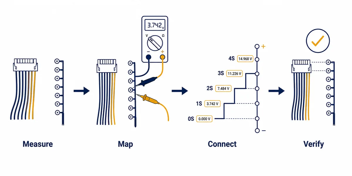
2. Map balance leads before plugging in the harness
With the balance connector unplugged from the BMS, identify the physical battery nodes first. In a four-series example, the reference node is usually pack negative and the next points are the junctions between cell groups, ending at pack positive. Measure adjacent nodes and also record cumulative readings from the reference. The exact voltage depends on chemistry and state of charge; the important safety signal is a coherent, explainable progression.
A wrong result is useful evidence, not a reason to force the connector. A negative step can mean reversed probes or a wrong reference. A near-zero step can indicate a duplicated node, open lead or poor contact. A step near two cell-group voltages can mean a junction was skipped. If one pin shows the full pack voltage where it should not, stop and remap the connector orientation.
- Label battery nodes before labeling connector wires; connector views can be mirrored.
- Use a stable meter reference and prevent probes from bridging adjacent pins.
- Write down adjacent and cumulative readings so another person can review them.
- Do not use the BAT BMS app to discover a wiring mistake after the board is energized.
| Meter result | Possible meaning | Decision |
|---|---|---|
| Consistent positive steps | Series map may be coherent | Compare with the exact DALY document before connection |
| Negative step | Polarity, probe direction or lead order problem | Stop and identify the reference node |
| Near-zero step | Duplicate junction, open lead or poor contact | Inspect the cell connection and harness |
| About two cell groups | A junction may be skipped | Remap the physical nodes |
| Full pack voltage at a wrong pin | Connector orientation or pin mapping error | Do not insert the balance plug |
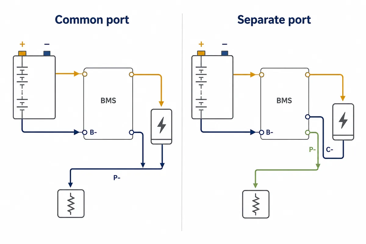
3. Confirm B-, P- and C- port roles
Many low-side BMS boards use B- for the pack-negative connection. P- commonly carries the protected load-negative path. On a common-port design, charger negative may share P-. On a separate-port design, charger negative may use C- while the load remains on P-. These are recurring patterns, not permission to bridge terminals or assume that every DALY model uses the same current rating.
Port errors can look like a dead battery. A board may block discharge while allowing a charger path, or it may require a documented wake-up condition before P- becomes active. Before blaming a charger, inverter or motor controller, confirm the expected negative terminal, protection state, cable size and fuse arrangement. Never bypass protection by joining B- and P-.
- Treat B-, P- and C- as model-defined terminals, not universal color codes.
- Check whether C- is charge-only and whether its current rating is lower.
- Use a fuse and cable size matched to continuous and surge current.
- Stop if the manual, silkscreen and measured path do not agree.
| Design | Charger negative | Load negative | Main check |
|---|---|---|---|
| Common port | Often P- | Often P- | One shared controlled path and its current rating |
| Separate port | Often C- | Often P- | Charge-port rating and protection rules |
| Unknown model | Do not guess | Do not guess | Find the exact DALY manual or stop |
4. Follow the documented DALY connection order
Once the node map is correct, follow the exact connection order for the board. Some designs require the main battery negative first, some specify a balance-plug sequence, and some add a temperature sensor, communication cable or precharge condition. A video for another DALY family can be useful for orientation, but it cannot replace the manual for the board in your hands.
For a first test, disconnect high-power loads and keep the work area clear. If the manufacturer permits it, use an appropriate fuse or current-limited setup and verify pack and output voltage with a meter before attaching a charger or inverter. A Bluetooth reading can confirm that the app sees plausible values, but it does not prove that polarity, cable gauge, fuse placement or terminal torque is safe.
- Check polarity at the pack, BMS and output terminals before applying power.
- Connect charger and load one at a time so a fault has a clear cause.
- Confirm that every expected cell group appears in the monitoring view.
- Stop for heat, smell, swelling, smoke or a rapidly changing reading.
5. Handle fewer cells, 4S examples and model variants
Searches for a Daly BMS wiring diagram often include 4S, 10S, 13S, 60A or a particular J-series model. Keep the series count separate from current rating. A 4S pack has four series positions; a 4S2P pack still has four sensing steps, but parallel cells, matching, thermal design and current demand change. A 10S or 13S board needs a different sensing boundary and cannot be treated as a longer version of a 4S harness.
Some DALY models support a documented lower cell count or a particular sequence, while others do not. Leaving a balance wire unused because a forum post says it is fine can create missing or incorrect cell readings. Use the model manual, not the number of holes in a connector, to decide whether a reduced series count is supported.
- Series count determines the cumulative sensing boundary.
- Parallel count affects capacity, current, matching and thermal behavior.
- Current labels such as 60A do not identify the correct balance sequence.
- A J-series model number must be matched to its own drawing and connector view.
| Search phrase | Best use on this page | Why it is not a separate page here |
|---|---|---|
| Daly BMS 60A diagram | Model-specific example and caution | Current rating alone does not define the wiring |
| Daly J13G3 / LE21 manual wiring | Manual lookup and connector-orientation FAQ | The exact revision still controls the pinout |
| Daly BMS wiring less cells | Edge-case warning | Only an approved reduced-series configuration is safe |
| 4S or 10S BMS wiring | Series-count comparison | Use a page or board that matches the actual count |
6. Stop when the diagram or measurements disagree
Do not continue when the board model cannot be identified, the pack has damaged insulation, a cell is swollen, terminals are burned, a previous repair is undocumented or voltage changes unexpectedly. Lithium packs can deliver destructive fault current even when the nominal voltage looks modest. Put the pack in a safe state and ask the manufacturer or a qualified battery technician when the evidence is incomplete.
A good Daly BMS wiring diagram reduces guessing; it does not remove the need for an exact manual, a meter and a controlled first power-up. Keep the board photo, connector map, readings and source document together. If you cannot explain every connection before power is applied, leave the harness disconnected.
- Stop for unknown model identity, damaged insulation or unexplained repairs.
- Do not bypass BMS protection to force an output.
- Treat swelling, heat, smoke and odor as reasons to isolate the battery.
- Ask for qualified help when the wiring evidence is incomplete.
Daly BMS Wiring FAQ
Is every Daly BMS wiring diagram interchangeable?
No. DALY has multiple BMS families, chemistries, series counts, current ratings and connector arrangements. Treat the model manual and board labels as the final authority, even when two harnesses have the same number of wires.
Can I connect a Daly BMS by wire colors only?
No. Colors can change between suppliers, revisions or connector views. Map the physical battery nodes, measure the balance sequence with the harness disconnected and compare the result with the exact board diagram.
What do B-, P- and C- mean on a Daly BMS?
B- commonly identifies the battery-negative connection. P- often carries the protected load-negative path, while C- may be a charge-negative path on a separate-port design. The exact use and rating remain model-specific; never bridge terminals to bypass protection.
How many balance leads does a Daly BMS need?
The number follows the supported series count and the board's sensing design. A four-series example commonly has five cumulative nodes, often described as B0 through B4, but the connector packaging and labels must be checked against the exact manual.
Can I use a Daly BMS with fewer cells than the connector supports?
Only when the exact model documentation explicitly supports that series count and connection order. Do not leave a wire unused because a forum diagram suggests it; missing sensing nodes can produce incorrect readings and unsafe protection behavior.
Why does a newly wired Daly BMS show no output?
Possible causes include a wrong balance sequence, incorrect connection order, active undervoltage or overcurrent protection, a missing wake-up condition, an open lead or a real board fault. Recheck the measured map and model-specific recovery procedure; do not join B- and P- to force output.
Technical references
- DALY BMS wiring tutorial - Use the model-specific diagram and balance-wire sequence as the primary hardware reference.
- DALY official support and product documentation - Confirm the exact model, connector orientation and revision before applying a generic pattern.
- Texas Instruments battery-management overview - Background context for cell monitoring, protection and battery-management functions.